RCCN WeChat QrCode
 Mobile WebSite
Voltage transformer wiring and circuit solutions, voltage transformer common problems and solutions ---- voltage transformer role
The purpose of the voltage transformer voltage conversion is mainly used to power the measuring instrument and relay protection device, used to measure the line voltage, power and power, or used to protect the line in the line when the protection of expensive equipment, motor And transformers, so the voltage transformer capacity is very small, generally only a few volts, tens of volts, the maximum is not more than a thousand volts.
Voltage transformer wiring and circuit solutions, voltage transformer common problems and solutions ---- voltage transformer works
Voltage transformer works the same as the transformer, the basic structure is the core and the original, the secondary winding. Features are very small and relatively constant, normal operation close to the no-load state.
Its working principle and the same transformer, the basic structure is the core and the original, the secondary winding. Features are very small and relatively constant, normal operation close to the no-load state. The impedance of the voltage transformer itself is very small, once the secondary side of the short circuit, the current will grow sharply and burn the coil. To this end, the voltage transformer of the primary side of the fuse, the secondary side of the ground, to avoid the original, secondary insulation damage, the secondary side of the high potential caused by personal and equipment accidents.
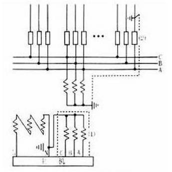
Measuring voltage transformers are generally made of single-phase dual-coil structure, the primary voltage for the measured voltage (such as the power system line voltage), can be used in a single phase, you can also use two VV-shaped three-phase use. Laboratory voltage transformers are often used to tap the tap to accommodate the need to measure different voltages. For the protection of ground voltage transformer also comes with a third coil, called the three coil voltage transformer. The three-phase third coil is connected to an open triangular shape, and the two leading ends of the open triangular are connected to the voltage coil of the ground protection relay.
During normal operation, the three-phase voltage of the power system is symmetrical and the sum of the three-phase induced electromotive force on the third coil is zero. In the event of single-phase grounding, the neutral point of displacement, open the triangle between the terminals will appear zero sequence voltage relay action, so as to protect the power system.
The coil appears zero sequence voltage is the corresponding core will appear zero sequence flux. To this end, this three-phase voltage transformer using side yoke (10KV and below) or using three single-phase voltage transformer. For this transformer, the accuracy of the third coil is not demanding, but requires a certain over-excitation characteristics (that is, when the primary voltage increases, the core of the magnetic flux density increases corresponding to the number of times without damage). [3]
Voltage transformer is a power plant, substation and other transmission and power supply system indispensable kind of electrical appliances. Precision voltage transformers are used in electrical testing laboratory to expand the limit, measuring voltage, power and power of an instrument. Voltage transformers and transformers are very similar, are used to transform the voltage on the line.
Why do I need to change the voltage on the line? This is because according to the different circumstances of power generation, transmission and electricity, the voltage on the line size varies, and the difference between the poor, some low voltage 220V and 380V, some high pressure tens of thousands of volts or even hundreds of thousands of volts. To directly measure these low and high voltage, it is necessary to produce the corresponding low voltage and high voltage voltmeter and other instruments and relays according to the line voltage. This will not only bring great difficulties to the production of the instrument, and more importantly, to directly produce high-voltage instruments, directly on the high-voltage lines to measure the voltage, it is impossible, but also absolutely not allowed.
Voltage transformer wiring and circuit solutions, voltage transformer common problems and solutions ---- commonly used voltage transformer wiring
1) General voltage transformer according to the use of points: for measurement and protection
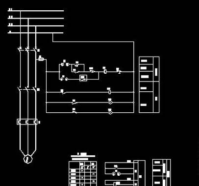
There are many ways to connect the voltage transformer, the following are common:
With a single-phase voltage transformer to measure a relative ground voltage or phase voltage of the wiring.
2. With two single-phase transformer connected into an incomplete star, also known as V-V wiring, used to measure the voltage between the phase, but can not measure the relative voltage, widely used in the following 20KV neutral ground or by the discharge The coil is connected to the grid.
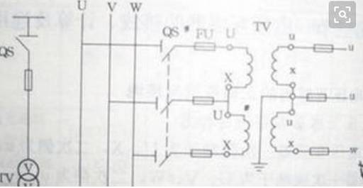
3. Three single-phase three-winding voltage transformers constitute YN, yn, d0 or YN, y, d0 wiring form, widely used in 3 ~ 220KV system, the secondary winding used to measure the phase voltage and the relative voltage , Auxiliary secondary winding connected into the opening triangle for access to AC power grid insulation monitoring instruments and relays. With a three-phase five-column voltage transformer instead of the three single-phase three-winding voltage transformer wiring, in addition to the core, the form and Figure 3 is basically the same, generally only for 3 ~ 15KV system.
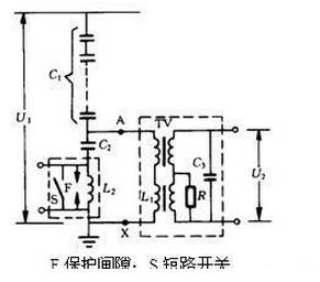
2, the application of capacitive voltage sensor can be used in high voltage and ultra high voltage power system for voltage and power measurement, energy metering, relay protection, automatic control, etc., and doubles as a coupling capacitor for power line carrier communication system. On request, internal accessories and external terminals for harmonic voltage measurements are available.
4. Capacitive voltage transformer wiring form.
In systems where the neutral point is not grounded or grounded by the arc suppression coil, the PT primary winding must be grounded in order to measure the relative voltage.
Voltage transformer wiring and circuit solutions, voltage transformer common problems and solutions ---- voltage transformer common exception
(1) three-phase voltage indication imbalance: a phase reduction (can be zero), the other two normal, line voltage is not normal, or accompanied by sound, optical signal, the transformer may be high or low voltage fuse blown;
(2) neutral non-effective grounding system, three-phase voltage indication imbalance: a phase reduction (can be zero), the other two phases rise (reachable line voltage) or pointer swing, may be single-phase ground fault or base Frequency resonance, such as three-phase voltage rise at the same time, and more than the line voltage (pointer can be placed in the head), it may be frequency or high frequency resonance;
(3) high-voltage fuses multiple fuses, may be serious damage to the internal insulation, such as winding layer or inter-turn short circuit fault;
(4) Neutral point effective grounding system, bus switching operation, the phase voltage rise and low-frequency swing, the general series resonance phenomenon; if there is no operation, suddenly appear phase voltage abnormal increase or decrease, it may be Insulation inside the transformer damage, such as insulation bracket around the winding layer or inter-turn short circuit fault;
(5) Neutral point effective grounding system, the voltage transformer put into operation when the voltmeter indicates instability, may be high voltage winding N (X) terminal ground contact bad.
(6) voltage transformer circuit disconnection processing.
Voltage transformer wiring and circuit solutions, voltage transformer common problems and solutions ---- voltage transformer exception handling methods
1. According to the relevant provisions of relay protection and automatic devices, exit the protection, to prevent malfunction.
2. Check the high and low voltage fuses and automatic air switch is normal, such as fuse blow, should identify the reasons for immediate replacement, when the fuse should be dealt with again.
3. Check the voltage circuit all the joints are loose, broken phenomenon, switching circuit with or without contact bad phenomenon.