RCCN WeChat QrCode
 Mobile WebSite
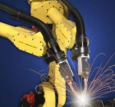
The vast majority of modern robots are model-based controls, and there are errors in the place where the model is located, so how much error is needed to compensate / calibrate depends on what model you use.
Rough, you can use the robot model is divided into two categories that kinematics model and dynamic model, so the error can be divided according to this:
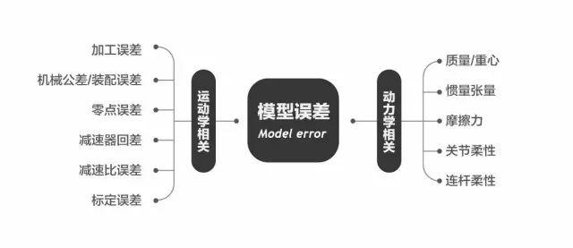
Sub-item simple to say.
Machining errors can result in:
The length of the connecting rod between the joints of the robot is not allowed;
With the surface is not accurate caused by some parameters designed to 0 into a non-zero;
Mechanical tolerances: Limited to machine tool machining accuracy and processing costs, mechanical parts will be left in the design of the tolerance, these tolerances may lead to assembly:
The joint theoretical axis does not conform to the actual axis;
The relative position between the adjacent links / structures deviates from the design;
Zero error: the size depends mainly on the zero calibration algorithm, the zero point is not allowed to cause the controller to calculate the theoretical model and the actual robot position does not match the calculation of the results are not accurate. 【☞ Robot zero calibration method】
Reducer hysteresis: mainly in the joint reverse when the impact of absolute positioning accuracy, and for the repeated positioning accuracy has no effect, and small robots commonly used in the Harmonic Drive known as zero backlash, the request is not high can not be considered.
Reducing ratio error: refers to the actual reduction ratio of the reducer and the manufacturer nominal there are small differences, interested students can design a simple device measured that the motor may need to go to the order of the order of 1 million.
Calibration error: refers to the robot in the course of the camera involved in the calibration (hand-eye calibration), tool calibration, workpiece calibration, etc., limited by the simple calibration device and streamlined calibration process, in fact, the biggest error is often from This aspect.
The above kinematic error identification has a lot of related research, the main work in the project to achieve and balance the cost, accuracy and ease of use between the relationship, not repeat them.
In terms of dynamics, mass, centroid and inertia tensor belong to the category of rigid body kinematics, and the research on its parameter identification is also sufficient.

Friction is a thorny problem, the main use is static friction, Cullen friction and viscous friction, a simple point to engage in a linear or second-order model, complex some can consider stribeck, and then no contact with the complex, mainly A long tune & test process, and each robot is not the same.
Static friction, then only the motor end position sensor, then can not determine its direction, the need for joint-side sensor, to increase the cost.
Requirements of higher occasions can not only consider rigid body dynamics, but also consider some of the joints and connecting rod flexibility, mainly using the identification method, the difference lies in how the model set the complexity.
The error of the kinetic parameters will greatly affect the effects of Feedforward, Gravity Compensation, and Compliance Control. If you do kinetic work, you need to consider identifying and compensating for the above errors.