RCCN WeChat QrCode
 Mobile WebSite
In order to ensure the safety of the battery system design process, in addition to the battery characteristics, battery module design, battery pack structure and exhaust design, it is necessary to count the number of battery management system. Here want to do a series of articles, respectively, introduced the basis of battery management system, passenger car management system, electric bus management system and battery management system development of four parts, this is the first.
From the nickel-metal hydride battery, the battery because of its own characteristics, the need for battery management system to manage, it is also the overall structure of the new energy vehicles one of the elements. On the whole, the main purpose of the battery management system is to measure the battery status and extend the battery life. Battery management system common function module according to the initial division, can also be divided into measurement function, the state calculation function, the system auxiliary function and communication and diagnosis.
The first part of the measurement function
1) basic information measurement: battery voltage, current signal monitoring, battery pack temperature detection
Battery management system has the most basic function is to measure the battery voltage, current and temperature, which is all battery management system top layer calculation, control logic basis. As shown in Figure 1, the battery management system is currently from the battery here to obtain the direct physical parameters is only voltage, temperature and current.
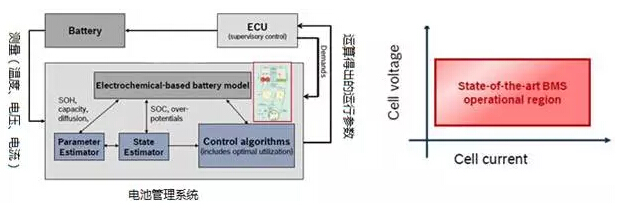 Figure 1 Overview of the battery management unit
1.1 Single voltage measurement and voltage monitoring
Single voltage, for the battery management system has several meanings, one can be used to accumulate the entire voltage, the second is based on the monomer voltage differential to determine the monomer difference, the third can be used to detect the operation of the monomer status. Single voltage acquisition and protection, are currently used to complete the ASIC, and consider the accuracy of the acquisition voltage not only need to consider the accuracy of the ASIC circuit itself, but also need to consider the single voltage sampling harness, wire harness protection fuse, balanced state Multiple content. Due to the sensitivity of the voltage acquisition accuracy, and the battery chemistry and SOC range (SOC both ends of the demand is often higher) have a relationship, in fact, ASIC data collected by the need to restore the voltage close to the battery itself.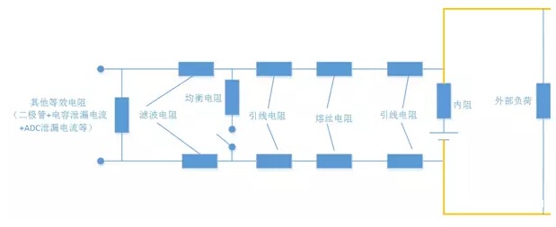
Figure 2 monomer acquisition circuit model
1.2 Battery pack voltage measurement
In the subsequent calculation of the SOC, the battery will often be used to calculate the total voltage, which is an important parameter to calculate the parameters of the battery pack; if the accumulation of individual voltage from the measurement of the battery voltage alone, there is a certain time difference , There is no way with the battery sensor data to achieve accurate alignment, so often collect battery pack voltage as the main parameters to operate. In the diagnosis of the relay, it is necessary to compare the voltage inside and outside the battery pack, so here generally measure the battery pack voltage at least two V0 and V1, as shown in Figure 3.
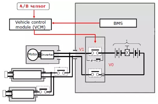
Figure 3 BMS high pressure acquisition
Because it involves a high-pressure collection, the need for isolation, so there are two general methods, such as AVGAO chip solution or through the resistance divider, and then configure the operating point, plus the car-level op amp composed of instrument op amp Circuit, as shown in Figure 4 below.
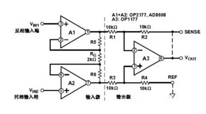
Figure 4 three op amp composed of instrument op amp
1.3 battery temperature
Temperature on the battery parameters have a great significance, here is also a controversial place. In the design of the battery and the module, the battery inside and outside the temperature difference, the battery pole and bus welding, the module within the battery temperature difference and the maximum temperature difference between the battery pack, these parameters in the design of the entire battery pack are already Carry out early control. BMS in the design of the temperature sensor placement point, and how many temperature points and the final collection of the temperature points to represent the operation of the entire battery pack, here is not BMS can manage the category. Temperature detection accuracy is also very particular about, such as in the -40 degrees, the detection accuracy does not need particularly high, because the use of the battery system itself requires heating, and -10 degrees to 10 degrees on the battery performance has a significant impact on the area , There are 40 degrees high temperature approaching, these are the need to focus on the area. In the design process, you can use the pull-up resistor, filter resistor and temperature sensor itself, the value of Monte Carlo analysis.
It should be noted that in a battery pack placed too much temperature sensor is not a good idea, with too many not only related to the diagnosis of the problem, but also through the analysis need to select more high-precision resistance, the cost is useless. ASIC circuit will now cover the function of temperature collection.
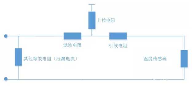
Figure 5 temperature acquisition circuit
1.4 battery pack fluid temperature detection
Battery management system in the entire battery pack inside the thermal control, the general role is to report the temperature, as well as the fluid inlet and outlet temperature, detection circuit and monomer detection similar.
1.5 Current measurement
Battery packs are often only in the monomer level to do parallel (the most extreme is Tesla's small battery 75 parallel), the battery pack in series to the unit to provide electricity, so generally only need to measure a current The Current measurement means mainly divided into two kinds of intelligent shunt or Hall current sensor. Since the current value of the battery system needs to be processed, it is often instantaneous, such as the discharge current required for acceleration of the vehicle and the charge current during energy recovery. Therefore, the range of the output current (discharge) and the input current (charge) Accuracy, which is a need to carefully check the work. Current is caused by the main reason for the monomer temperature changes, the role of resistance and chemical heat together constitute the battery heat; current changes will also cause changes in voltage, together with the time, these three are accounting for the state of the battery elements The
Hall sensors at the beginning of the Japanese hybrid used more, and now slowly have a smart shunt to complete the voltage and current sampling, through the serial bus transmission, and even inside the SOC can be estimated.
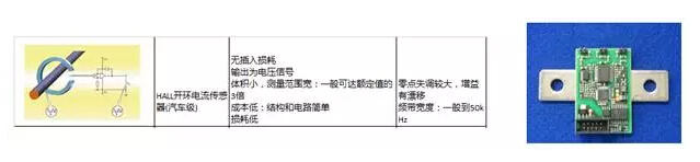
Figure 6 two current sensors
2) Insulation resistance detection
Battery management system, the general need for the entire battery system and high-voltage system for insulation testing, the more simple is to rely on the bridge to measure the bus positive and negative on the ground insulation resistance. Now in the battery bag inside the more active signal injection, the main can detect the battery on the system insulation resistance.
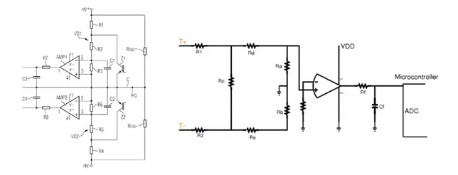
Figure 7 Passive insulation detection
3) High voltage interlock detection (HVIL)
The purpose of the high-voltage interlock is to confirm the integrity of the entire high-pressure system, when the high-voltage system circuit is broken or the integrity of the destruction of the time, you need to start the security measures.
A) The presence of HVIL allows the integrity of the entire system to be known before the high-voltage bus is powered on, that is, before the battery system's main and negative relays are closed to power
B) the presence of HVIL is required for the entire system, mainly through the connector on the low-voltage connection circuit to complete, the battery management unit generally need to provide the circuit detection circuit.
HVIL sources come in three different ways, 5V, 12V and PWM waves.
The circuit here is a large piece of ASIC is completed, Figure 8 below illustrates the different ASIC circuits.
Figure 8 ASIC circuit development
The second part of the state estimation function
1) SOC and SOH estimates
The most difficult part of the battery system is the most difficult part of the SOC and SOH estimates. SOC estimation is common with an hourly integration method (SOCI), and open circuit voltage calibration method (SOCV), the biggest problem of Anshi integral is that the error will increase over time, the problem of open circuit voltage calibration is that the battery needs The SOC of the open circuit voltage after a long period of time is accurate, and the voltage collected by the vehicle is used to calibrate the SOC when it is not accurate. In actual use, SOCV is generally used as the main SOCI, in actual use is also using a certain Kalman filter, neural network method to improve the SOC calculation, but limited to the MCU computing speed and ability, the complexity of the algorithm There is a limit.
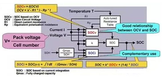
Figure 9 SOC and SOH estimates
2) Equilibrium
A series of battery packs, due to battery and battery management reasons, there will always be uneven phenomenon. In the actual use of the process, the output capacity of each series is not the same. The battery, not only over discharge and overcharge restrictions, but also in different temperatures and different SOC, the input and output power is also limited. That is, a single battery limit will affect the entire battery. This is not equal to a single overrun, it is equal to the entire insecurity, but that the battery will be damaged, the persistence of the problem.
1. Individual differences between individual cells in the battery pack: differences in monomer capacity, differences in monomer internal resistance, differences in self-discharge of the monomer, current difference during operation and current difference during sleep
2. Battery pack changes with time: monomer capacity difference, monomer internal resistance difference, monomer self-discharge difference
3. The customer uses the charging time, the discharge time
4. Self-discharge of the external environment with the temperature, self-discharge under different SOC
5. System interaction: BMS working conditions, this factor and the working status of BMS relationship.
Of course, we need to choose a balanced approach, including hardware topology and equalization algorithm in two parts, in the automotive industry applications, we have reliability, cost and security, and several other restrictions.
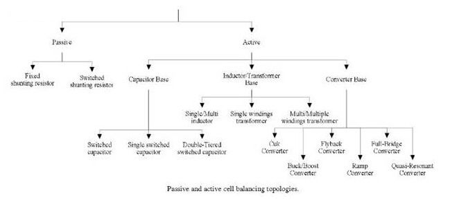
Figure 10 balanced way
3) Battery power limit
New energy vehicles in the battery capacity is different, lithium battery system for the vehicle, especially the motor to provide energy, need to meet the motor power requirements. And a certain capacity of the battery in a different SOC, different temperatures, the input and output power is a certain limit. The actual operation of the hybrid battery pack SOC window is very small, pure electric vehicle with a very wide, run out to end the use of plug-in hybrid battery exhausted when you need to consider the output power limit The The battery management system needs to be sent to the vehicle controller with a power limit parameter, which is calculated based on a 3D table containing temperature, SOC, battery capacity, as shown in Figure 11.

Figure 11 SOC control table
The third part of the auxiliary system functions
This part of the function, the general battery management system is to do the auxiliary use, often with the vehicle control system or other related systems for joint use.
1) relay control
Battery packs generally have multiple relays, the battery management system at least to complete the relay drive supply and status detection, relay control is often reconciled with the vehicle controller to confirm the controller, and the airbag controller output collision signal The relay controller is disconnected directly. Battery packs are generally the main relay, the main negative, pre-charge relay and charging relay, in addition to the battery pack there is a separate distribution box to make a more detailed protection of the current distribution. It is important to control the relay, the closing, the disconnected state of the battery pack, and the order of the switches.
2) thermal control
As mentioned above, the chemical properties of the battery by the ambient temperature is very large, in order to ensure the battery life must allow the battery to work within a reasonable temperature range, and according to the different temperature to the vehicle controller Output and input the maximum power. For the battery system temperature control is mainly used CFD simulation analysis, as mentioned above, the temperature sensor of this unit, how to use the least number of sensors to effectively monitor the entire battery pack temperature distribution, and monitoring information back to the battery management system and The entire battery temperature management system. Figure 12 shows the thermal analysis of the battery module. Figure 13 shows the cooling and heating systems of a liquid-cooled system, vehicle and battery system.

Figure 12 Thermal analysis of a module
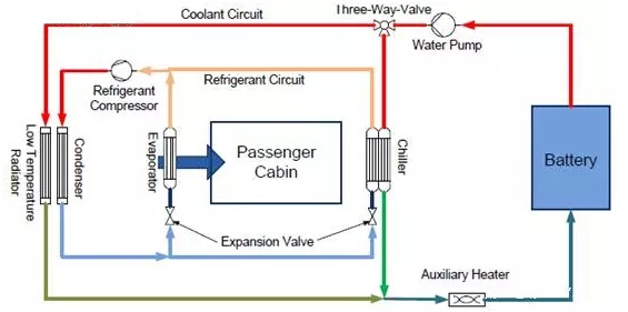
Figure 13 Battery system thermal control
3) charge control
One of the main modes of battery management systems is to monitor the battery requirements of the battery system during charging. In the AC system, the BMS needs to implement the PWM control pilot circuit interaction; in the DC charging process, in particular, need to pay attention to the higher SOC to allow the charge current. In the national standard system, the battery management system is required to directly communicate with the outside, the process of interactive charging information. Theoretically, the design of this feature can be moved to different modules, otherwise the battery management system sleep wake-up mechanism will be somewhat complicated.
The fourth part of communication and fault diagnosis
1) communication function
Battery management system, at least to the vehicle controller to send the battery system information; in a DC charging system, especially in the national standard system need to communicate directly with the external DC charging pile. At some point, there may be a backup of the diagnostic and refreshing communication lines, used in the case of main communication failure to do data transmission.
2) fault diagnosis and fault tolerance operation
Fault diagnosis and fault-tolerant control in any controller which is a very important part of the battery management unit failure will also need to fault code (DTC) to the alarm, through the DTC trigger dashboard lights in the new energy vehicles Battery failure also has a corresponding indicator to remind the driver. Due to the risk of the battery, it is often necessary to carry out the information transmission directly to the bus system to deal with the sudden occurrence of the accident. For example, when an accident occurs, when the airbag pops up, the relay is directly cut off by the vehicle controller, the car system through the positioning and early warning to deal with, especially the battery discharge. Fault diagnosis includes the battery voltage, battery pack voltage, current, battery pack temperature measurement circuit fault diagnosis, determine the fault location and fault level, and make the appropriate fault-tolerant control.
Fail-Safe fault-tolerant operating mechanism, refers to the vehicle in the course of running an error, the vehicle downgrade operation. In fact, this feature is more like all the above functions downgrade and backup.
summary:
1) battery management system features more complex, here to initiate, to be a systematic brief, followed by passenger cars and electric bus two content targeted examples and analysis.
2) battery system, do well and do bad, the essence is still a big difference, here is only given some basic elements, let everyone reference.
3) write more messy, follow the system into hardware and software alone look at the time, will be more clear some.