RCCN WeChat QrCode
 Mobile WebSite
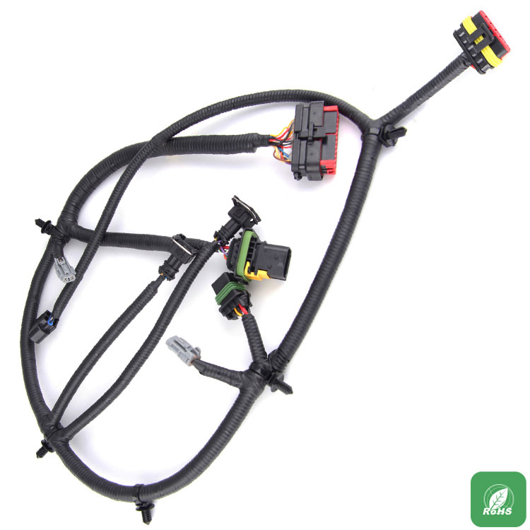
As a key component of Hyundai's car, the wire harness includes thousands of assembly elements that connect the various electronic systems together so that they can work together. Any wiring harness failure, may have an impact on the entire system. However, in order to cope with the growing demand for electronic systems within the vehicle, the complexity of automotive wiring harnesses is increasing, so we are more pressing to quickly and easily detect open circuit and short circuit. Line diagnostics are very important throughout the life of the vehicle. From the installation phase, diagnosing and repairing line faults can cause serious manufacturing delays. During the operation phase, diagnosing and repairing line faults can result in an increase in the number of car repairs, thereby significantly increasing the manufacturer's warranty costs.
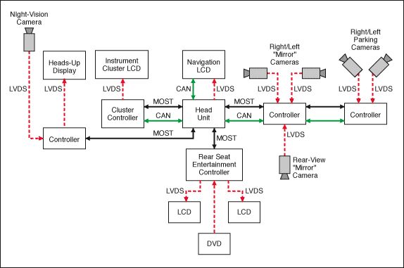
Active safety systems, including lane detection and parking assist systems (front and rear view cameras), as well as infotainment systems (including navigation and rear seat entertainment), are more concerned about the automotive electronics system. To make these systems run efficiently, video data transmitted from cables from any corner of the car must be reliably delivered to the driver and passengers. The health of the cables is critical to maintaining the proper operation of these systems.
The circuit shown in Figure 1 can effectively detect battery short circuit (STB), ground short circuit (STG), open circuit and short circuit fault. This circuit uses the ADA4433-1 (U1) fully integrated video reconstruction filter as part of the video transmission signal chain and also uses the ADA4830-1 (U2) high speed differential amplifier as the detection circuit. The ADA4433-1 incorporates a high-order filter with a -3 dB cutoff frequency of 10 MHz, 45-dB rejection at 27 MHz, and an internal fixed gain of 2 V / V. It has excellent video characteristics, provides overvoltage protection (OVP) and overcurrent protection (STG) on the output, and low power consumption. The ADA4830-1 provides an attenuation gain of 0.50 V / V and also provides a fault detection output flag indicating the presence of an overvoltage condition on its input. It provides up to 18 V input overvoltage protection with a wide input common-mode voltage range and excellent ESD stability.
In the example circuit shown in Fig. 1, U1 represents a differential output buffer which transfers the video signal from the rear view camera or the engine control unit (ECU) to the receiver. The input is usually driven by a CMOS imaging element or video encoder. U1's main function is to provide active filter function (reconstruction), and drive the video signal through the cable to the display of the transmission. The input of U2 is connected to the output of U1 to provide the fault detection function listed in Table 1, which is described in the following paragraphs.

Figure 1. Line diagnostics using ADA4433-1 (U1) and ADA4830-1 (U2).
Battery short circuit fault detection
Both U1 and U2 have integrated battery short-circuit detection and STB output. In the battery short-circuit event, the output flag of U2 will signal a logic low state, and the microcontroller's general-purpose input / output (GPIO) port can easily read the signal.
Ground short circuit fault detection (single output)
Connect the positive input (INP) of U1 to the negative input (INN). The differential output between OUT and -OUT should be 0V. If any of the outputs are shorted to ground, the differential voltage at U2 output should be greater than 500 mV.
Ground short-circuit fault detection (two outputs)
Set U1 positive input (INP) to 0V. The differential output between OUT and-OUT should be approximately 1V. If both outputs are shorted to ground, the differential voltage at U2 output is approximately 0V.
open circuit
Set U1 positive input (INP) to 0V. The differential output between OUT and-OUT should be approximately 1V. If there is a short open connection, the differential voltage at the output of U2 is about 500 mV.
Adjacent output short circuit
Set U1 positive input (INP) to 0V. The differential output between OUT and-OUT should be approximately 1V. If the two outputs are shorted together, the differential voltage at the output of U2 is about 0 V.
Normal operation (no cable fault)
Set U1 positive input (INP) to 0V. The differential output between OUT and-OUT should be approximately 1V. The differential voltage at the output of U2 is about 250 mV.