RCCN WeChat QrCode
 Mobile WebSite
[Terminal terminal] What is the terminal block? Type of terminal block How to wire the terminal block
What is a terminal block?
The terminal block is used to facilitate the connection of the wire. It is actually a piece of metal that is sealed inside the insulating plastic. There are holes at both ends to insert the wire, and screws are used for fastening or loosening, such as two wires, sometimes Need to connect, and sometimes need to disconnect, then you can connect them with the terminal, and can be disconnected at any time without having to solder or entangle them, it is convenient and quick. Moreover, it is suitable for a large number of wire interconnections. In the power industry, there are special terminal blocks, terminal boxes, all of which are terminal blocks, single layer, double layer, current, voltage, ordinary, breakable and so on. A certain crimp area is required to ensure reliable contact and to ensure sufficient current is passed.
Terminal type
1, plug-in
It is made up of two parts plugged and unplugged, one part is pressed and then inserted into another part, which is soldered to the PCB. This bottom mechanical principle, this anti-vibration design ensures long-term airtight connection and reliability of the finished product. The ears can be assembled at both ends of the socket. The mounting ears can largely protect the tabs and prevent the tabs from being placed in a poor position. At the same time, the socket design ensures that the socket can be correctly inserted into the maternal body. The socket can also have an assembly buckle and a locking buckle. The mounting buckles provide a more secure attachment to the PCB, and the locking tabs lock the parent and socket after installation. A variety of socket designs can be used with different mating methods, such as horizontal, vertical or tilted printed circuit boards, etc., depending on the customer's requirements. You can choose either a metric wire gauge or a standard wire gauge, which is the hottest terminal type on the market.
2, fence type
It is able to achieve safe, reliable and effective connection, especially in high current, high voltage environment.
3, spring type
It is a new type of terminal block that utilizes spring-loaded devices and has been widely used in the world's electrical and electronic engineering industries: lighting, elevator lifting control, instrumentation, power supply, chemical and automotive power.
4, track installation
Reliable threading technology, electronic fuse technology and the latest electrical connection technology are widely used in power electronics, communications, electrical control and power supply.
5, orbital
The use of crimping and a unique threaded self-locking design make the wiring connection reliable and safe. The series of terminal blocks are beautiful in design and can be equipped with a variety of accessories, such as shorting bars, marking strips, baffles, etc.
6, through the wall
The screw connection technology is adopted, the insulation material is PA66 (flame retardant grade: UL94, V-0), and the connector is made of high-quality high-conductivity metal material.
H-type through-wall terminal blocks can be installed side by side on panels of thickness from 1mm to 10mm, which can automatically compensate the distance of the adjustment panel thickness, form terminal strips of any number of poles, and can use spacers to increase air gap and creepage distance. The wall-mounted terminal block can be firmly installed in the rectangular reserved hole on the panel without any tools, and the installation is extremely convenient.
H-type through-wall terminal blocks are widely used in some applications where wall penetration solutions are required: power supplies, filters, electrical control cabinets and other electronic equipment. The insulation performance is good and the protection level is high. The user only needs to work directly after external wiring, which saves many unnecessary wiring steps. The modified series of insulating materials for UK series terminals are made of modified nylon (PA66), which can be connected to 4mm2 wire with a voltage of 800V and a current of 41A.
7, WMSTB
The PCB terminal is made of modified imported nylon (PA66), which has good electrical and mechanical properties. Whether you need hard wire and hard wire connection, hard wire and multi-strand wire, or multiple strands and more Strand connection
8, insurance terminals
Modified nylon (PA66) for insulating materials with good electrical and mechanical properties. The screws are made of high-strength copper alloy, the conductors are made of electrolytic copper, and the crimping frame is made of alloy copper which is resistant to stress cracking. These metal surfaces are also protected by tin or nickel plating. The all-copper terminal block avoids the battery effect of steel metal parts and copper wires in a humid environment. There is a connection hole in the middle of the terminal, and the center connection can also be connected by the side plug-in connection; it can be connected to the electrical product of 4mm2 wire voltage of 800V and current of 41A.
9, test terminals
The sliding metal member functioning as a switch can withstand the maximum working current through the terminal crimping frame. When switching, use a screwdriver to loosen the screw and move the slider. The switch position is clear at a glance; the test socket is provided at both ends, corresponding to the corresponding The test tip can be connected for testing and the current can be measured without interruption. It can be connected to a control circuit with a voltage of 660V and a current of 57A.
10, universal type
Color is gray terminal
Thickness: 6.2 wire cross section: 0.2-4:32A: 500V can be mounted on the U-shaped or G-type rail. The double-layer type terminal block has twice the wiring capacity of the universal terminal at the same position, and the upper and lower layers are designed. The 2.5mm space is staggered, not only visually well-defined, but also in the case of the upper wiring, the screwdriver can be easily wired in the lower area, and the marking is clear.
11, optical isolation terminal
The existing rail-type terminal frame screw connection technology is used, and a circuit composed of electronic components is added to realize the transmission coupling of the photoelectric process.
The core of automatic control is that the control unit must be reliably isolated from each sensor and actuator to avoid interference. The Sanmen Bay WUKG optical isolation terminal can do this well and ensure the low requirements of the on-site signal and electronic control device. The voltages are matched and can also be used as interface components between process control peripherals and control, signal and regulator devices, and for different voltage and power ranges.
The optical isolation terminal has the advantages of low signal loss at the control end, high switching frequency, no mechanical contact jitter, no wear switching, high insulation voltage, no fear of vibration, no position influence and long life, so it is widely used in the field of automatic control.
How to wire the terminal block
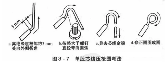
1. When the single-core wire is connected with the terminal block, it is better to fold the wire into double-stranded side-by-side pinholes according to the required length, so that the crimping screw is tightened on the double-core wire. In the middle, as shown in Figure 3-6a. If the thread is thicker, the double-strand core wire can not be inserted into the pinhole, and the single-strand core wire can be inserted directly, but the core wire should be slightly bent toward the top of the pinhole before inserting the pinhole, so as to avoid the compression screw. If there is a loose thread, it will come out, as shown in Figure 3-6b.
Whether it is a single-strand core wire or a multi-strand core wire, the wire head must be inserted into the hole when inserting the pinhole. The wire insulation layer must not be inserted into the hole. The length of the bare wire head outside the pinhole must not exceed 3 mmo. First tighten one near the orifice and tighten one near the bottom of the hole.
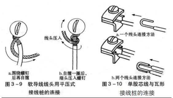
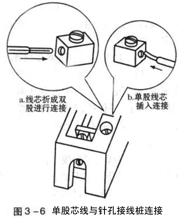
2. The connection between the single-core core wire and the screw flat-press type terminal of the connection between the wire end and the screw-type flat-type terminal is made by using a semi-circular head, a cylindrical head or a hexagonal head screw and a washer.
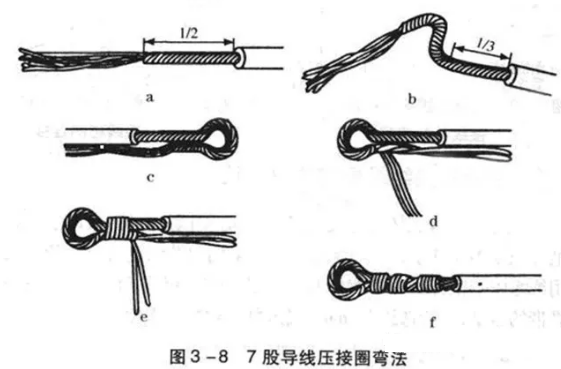
The head is pressed tightly to complete the connection. For a single-strand core wire with a small current carrying capacity, first bend the wire end into a crimp ring (commonly known as a sheep eye ring) and then press it with a screw. In order to ensure sufficient contact area between the wire end and the terminal block (terminal pile), it will not loosen or fall off for a long time, and the crimping ring must be rounded. The single-core core crimping ring bending method is shown in Figure 3-7.
For 7-strand and below multi-core wires with a cross-section not exceeding 10 mm2, the crimp ring shall be bent as shown in Figure 3-8. First, re-twist the core wire about 1/2 of the length of the insulating layer, the tighter the better, as shown in Figure 3-8a;
The core wire of the stranded portion is folded to the left outside at 1/3 of the root of the insulating layer, and then the arc is bent, as shown in Fig. 3-8b; when the arc is curved to form a circle (the remaining 1/4) The remaining core wire should be folded to the right and then rounded, and the remaining wire ends should be flattened so that the core wires at both ends are parallel, as shown in Fig. 3-8c; the scattered core wires are 2, 2 Root and 3 are divided into three groups, the first group of 2 core wires are erected, perpendicular to the core wire (to leave the width of the gasket edge, as shown in Figures 3-8d); Processing, as shown in Figures 3-8e. Figure 3 - 8f is a entangled seven-strand core wire crimping ring. For seven or more flexible conductor ends with a cross-section exceeding 10 mm2, lugs shall be installed.
The process requirements for connecting the crimping ring to the terminal block (terminal) are: the bending direction of the crimping ring and the connecting lug should be the same as the screw tightening direction; the oxide layer and the dirt on the crimping ring, the connecting lug and the gasket should be removed before the connection. Then place the crimp ring or lug under the washer and tighten the screw with the proper torque to ensure good contact. Do not insulate the wire into the person's gasket during crimping.