RCCN WeChat QrCode
 Mobile WebSite
The automatic train control system (ATC) is essential for the high efficiency and high density requirements of urban rail transit systems. One of the important subsystem train automatic driving (driving) systems (ATO) can simulate an experienced driver to complete the task of driving a train. The ATO subsystem uses ground information to control the traction and braking of trains, so that the trains are always in optimal operation, improve passenger comfort, improve trains' punctuality rate, and save energy.
Many countries are studying the ATO system and have achieved certain results. China is still a blank in this technology. This paper will compare and analyze the technical characteristics of three sets of ATO systems.
1 Introduction to ATC and ATO
ATC is an automatic control device that adjusts the train running interval for the purpose of safety and efficiency. The train operation control is completed by the control system consisting of the vehicle equipment, ground equipment, station and control center. The ATC system consists of three subsystems: the Automatic Train Monitoring System (ATS), the Automatic Train Protection System (ATP) and the Automatic Train Operation System (ATO).
The ATS subsystem implements supervision and guides the train to operate according to a predetermined schedule to ensure the stability of the subway operating system. It establishes a departure route through the conversion switch and provides the train with supervisory commands from the control center.
The ATP subsystem features overspeed protection, zero speed detection and door limits. ATP provides speed limit information to maintain a safe separation between trains, allowing the train to operate at standards that meet the speed limit. Before opening the door, the ATP first checks the conditions that allow the door to be opened. After the inspection is passed, the door is allowed to open.
The ATO subsystem automatically adjusts the speed of the vehicle and can perform fixed-point parking within the station, allowing the train to stop at the correct position of the station.
The ATO receives the train operation mission command from the ATS. The information is transmitted to the train via a track circuit or trackside communicator. The information is processed and passed to the ATO and displays relevant information. After the ATO obtains useful information, it starts to calculate the running speed in combination with the line condition, obtains the control amount, and executes the control command while displaying the relevant information. After arriving at the station, the ATO opens the door after the door opening conditions permit. During the stop, the train transmits the train information to the terrestrial communicator via the car-ground communication system and then to the ATS. The ATS transmits the operational information to the onboard ATO based on the train information. The working principle of ATO is shown in Figure 1.
Figure 1 ATO working principle diagram
2 ATO system technical characteristics comparison
In the early 1990s, part of the Beijing Metro Line 1 train installed ATO equipment from the UK Westinghouse (unused); the ATO equipment of Shanghai Metro Line 1 was introduced from the US GRS company and began in November 1996. Try it all over the line. The Guangzhou Metro Line 1 introduced the ATO equipment of the German company Siemens, which was officially opened in June 1999. Because their ATO system design is not the same, it is necessary to compare different places (mainly ATO equipment, ATO demand data and transmission channels and control strategies), and then analyze the characteristics of various designs to facilitate ATO equipment. Localization.
2.1 Beijing Metro Line 1 ATO System
1.ATO equipment
Vehicle-mounted equipment: consists of an ATO controller located in the driver's cab at each end of the train and two ATO receiving antennas installed under the driver's cab at each end of the train and two ATO transmitting antennas.
Ground equipment: A station ATO communicator PAC (Platform ATO Communicator) is installed in each station equipment room. The PAC has the line information to the next two stations, and through the interface with the LPU or RTU, the control commands from the ATS subsystem are obtained. An Xd or X2 loop and an Rd loop are provided on the up and down stations of each station and the track on the return line where the ATO is folded back. During the parking of the train, the train is sent to the outdoor loop through the relevant conditions of the interlock circuit and the track circuit.
2. ATO demand data and transmission channel
In the process of ATO data acquisition, the vehicle ATP receives safety information. The safety information is transmitted by the AF900 track circuit of the current running section of the train. It uses low-frequency pulse amplitude modulation, with 8 different modulation frequencies, 6 for ATP speed commands, and 2 for gated commands. In addition, the onboard TWC system receives terrestrial TWC information. This information is typically non-safety control function data such as run level, train number, destination, and trip. This information is transmitted to the train via the ground TWC device using FSK modulation. Finally, the onboard ATO receives information from the vehicle ATP, TWC and the marker coil.
3. Control strategy
Speed adjustment: The ATO calculates the train running speed curve based on the MSS and TS obtained from the ATP. The curve is relatively simple, mainly calculating the position of the acceleration and the uniform speed and the uniform speed to brake, so as to ensure that the train does not exceed the MSS when running, and the speed does not exceed the target speed at the target distance of each track circuit section. The controller automatically controls the traction and braking output of the train according to the condition of the line, and tries to make the train run at the speed of the running speed curve. When the train speed exceeds the target speed, the ATP device alarms; when the maximum allowable speed is exceeded, the ATP performs emergency braking.
Station parking: Positioning parking at the station is achieved through the X2 and Xd loops. After the train enters the X2 loop area of the station, the distance from the parking point is obtained through the induction between the ground and the vehicle, and the first position adjustment is performed, and the speed is as close as possible to the preset parking speed curve. At the Xd loop, the second and last position adjustment is made.
Analysis and Design of Automatic Train Operation System of Subway Train
Related articles
-
Pakistan ushered in the first "Made in China" subway
In May this year, held in May this year,"all the way"International Cooperation Summit Forum, led by the China Railway Corporation and the North Industrial Company joint package of China-Pakistan Econo
-
"Made in China" subway will be exported to the United States the first train off the assembly line
Walk into the car to feel the details of the designSubway exports to the United States on China's related industries and even national manufacturing industry has great significance. Boston is a city w
-
Build rail transit world-class manufacturing cluster
The rail transit industry represented by high-speed rail and heavy-duty locomotives has become a business card in the world renowned in China. In the new era, how is the rail transit industry going fo
-
China's first batch of the highest level automatic subway train put into operation
Beijing Yan Line subway train officially put into operation. This is the first batch of metro vehicles in mainland China that have reached the world's highest level of automation and can realize unatt
-
What are the advantages of linear motors in the subway track system?
With the rapid development of China's cities, transportation has become a bottleneck for the further development of the city. As a fast and safe, and large-capacity urban transport, the subway is an i
-
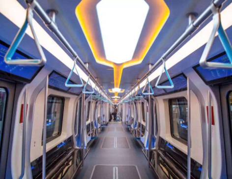
The next generation of subway trains is about to be brand new. The interior of the car is illuminated by LED lighting.
“The appearance is beautiful, the interior of the car is illuminated by LED, creating an atmosphere full of futuristic technology. Some windows are embedded with OLED multimedia display screens...” Wa
-
China Railway Construction cracks the fastest subway in China
Recently, the China Railway 14th Bureau of China Railway Construction successfully applied the high-speed rail CRTSIII track board to the construction of the Beijing New Airport Line subway, which sol
-
Analysis and Design of Automatic Train Operation System of Subway Train
The automatic train control system (ATC) is essential for the high efficiency and high density requirements of urban rail transit systems. One of the important subsystem train automatic driving (drivi