RCCN WeChat QrCode
 Mobile WebSite
Switching power supply overcurrent, short circuit protection principle
Overcurrent short circuit is actually a principle, through the output in series with a detection resistor, the need to protect the current value into a voltage value, the voltage into the op amp, compared with the reference voltage, you can get a signal, Used to control whether the protection is started. Overcurrent can be protected, and that short circuit is the overcurrent limit state, but at this time due to short circuit, the output voltage is not, then with the primary MOSFET current limiting resistor to control the maximum output power, you can achieve short circuit protection.
Common power protection circuit analysis
Evaluation of the quality of switching power supply should be based on safety, reliability as the first principle. In the electrical technical indicators to meet the normal requirements of the conditions, in order to make the power supply in harsh environments and sudden failure to work safely and reliably, you must design a variety of protection circuits, such as anti-surge soft start, overvoltage, undervoltage , Overheating, overcurrent, short circuit, lack of equal protection circuit. Switching power supply commonly used several protection circuits are as follows:
1, anti-surge soft start circuit
Switching power supply input circuit mostly use capacitor filter rectifier circuit, in the line power closing moment, because the capacitor on the initial voltage is zero, the capacitor will instantly charge a large inrush current, especially high-power switching power supply, using Large capacity of the filter capacitor, the surge current of 100A or more. In the instantaneous power surge instantaneous surge current, heavy often lead to the input fuse blown or closing switch contact burned, rectifier bridge overcurrent damage; light will also make the air switch on the gate. The above phenomenon will cause the switching power supply can not work properly, for which almost all of the switching power supply are set to prevent the current surge soft circuit, to ensure normal and reliable power operation.
Figure 1 is the use of thyristor V and current limiting resistor R1 composed of anti-surge current circuit. When the power is turned on, the input voltage is charged to the capacitor C via the rectifier bridge (D1 ~ D4) and the current limiting resistor R1 to limit the inrush current. When the capacitor C is charged to about 80% of the rated voltage, the inverter is operating normally. Through the main transformer auxiliary winding thyristor trigger signal, the thyristor conduction and short circuit current limiting resistor R1, switching power supply in normal operation.

Figure 1 using a thyristor and current limiting resistor composed of soft start circuit
Figure 2 is the use of relay K1 and current limiting resistor R1 constitute the anti-surge current circuit. When the power is turned on, the input voltage is rectified (D1 ~ D4) and the current limiting resistor R1 to charge the filter capacitor C1 to prevent the instantaneous surge current. At the same time, the auxiliary power supply Vcc is connected to the relay K1 Capacitor C2 charging, when the voltage on the C2 to reach the operating voltage of the relay K1, K1 action, the contact K1.1 closed bypass current limiting resistor R1, the power into the normal operation of the state. The delay time of the current limit depends on the time often (R2C2), usually selected as 0.3 ~ 0.5s. In order to improve the accuracy of the delay time and to prevent the relay jitter oscillation, the delay circuit can be used to replace the RC circuit shown in Figure 3 circuit.

Figure 2 using the relay K1 and current limiting resistor composed of soft start circuit

Figure 3 replace the RC delay circuit
2, overvoltage, undervoltage and overheat protection circuit
The power supply overvoltage and undervoltage on the switching power supply caused by the hazards, mainly in the device due to withstand the voltage and current stress beyond the scope of normal use and damage, while the electrical performance indicators are destroyed and can not meet the requirements. Therefore, the upper and lower limits of the input power supply should be limited, for which the use of overvoltage, undervoltage protection to improve the reliability and safety of power.
Temperature is the most important factor affecting the reliability of power supplies. According to the relevant data analysis shows that the electronic components of the temperature rise of 2 ℃, the reliability decreased by 10%, the temperature rise of 50 ℃ when the working life is only 1/6 of the temperature rise of 25 ℃, in order to avoid damage to the power device overheating, Switching power supply also need to set the overheat protection circuit.
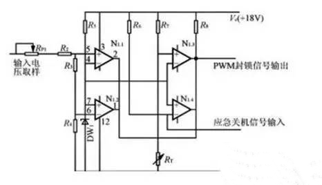
Figure 4 overvoltage, undervoltage, overheat protection circuit
Figure 4 is only a 4 comparator LM339 and several discrete components of the overvoltage, undervoltage, overheat protection circuit. The sampling voltage can be obtained directly from the auxiliary control power rectifier filter, which reflects the input power supply voltage changes, the comparator share a reference voltage, N1.1 for the undervoltage comparator, N1.2 for the overvoltage comparator, adjust R1 can be adjusted Over and undervoltage action thresholds. N1.3 for the overheating comparator, RT is a negative temperature coefficient of the thermistor, it and R7 constitute a voltage divider, close to the surface of the power switching device IGBT, the temperature increases, RT resistance decreased, the appropriate choice of R7 Resistance, so that N1.3 in the set temperature threshold action. N1.4 for external fault emergency shutdown, when the positive input to the low level, the comparator output low block PWM drive signal. As the output of the four comparators is connected in parallel, either overvoltage, undervoltage, overheating, any of the faults occur, the comparator output is low, and the drive signal is blocked to stop the operation and protection. If the circuit is slightly changed, can also make the comparator output high-level block the drive signal.
3, lack of protection circuit
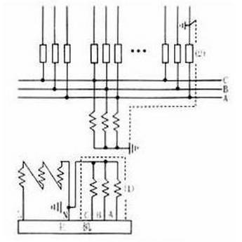
Due to the reasons for the power grid itself or power input wiring is not reliable, switching power supply sometimes there will be phase loss operation, and out of phase operation is not easy to be found. When the power supply is in phase loss, there is no current in the arm of the rectifier bridge, and the other arm can cause serious overcurrent damage, and the inverter is working abnormally. Therefore, the phase must be protected. Detection of power shortage phase is usually used current transformer or electronic phase detection circuit. As the current transformer detection costs are high, bulky, so the switching power supply is generally used in electronic phase protection circuit. Figure 5 is a simple electronic phase loss protection circuit. When the three-phase equilibrium, R1 ~ R3 node H potential is very low, the optical coupling output is approximately zero level. When the phase is missing, H point potential elevation, optocoupler output high level, compared by the comparator, the output low, block the drive signal. The reference of the comparator is adjustable in order to adjust the phase loss action threshold. The phase protection is suitable for three-phase four-wire system, not for three-phase three-wire system. The circuit changes slightly, you can also use high-level block PWM signal.

Figure 5 three-phase four-wire system of the lack of protection circuit
Figure 6 is a three-phase three-wire power supply phase loss protection circuit, A, B, C lack of any phase, the output level of the optocoupler is lower than the comparator inverting input reference voltage, the comparator output low Flat, block the PWM drive signal, turn off the power. Comparator input polarity slightly changes, can also be used to block high-level PWM signal. This phase-loss protection circuit uses optocoupler isolation strong power, safe and reliable, RP1, RP2 used to adjust the phase protection action threshold.
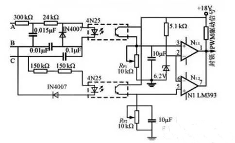
Figure 6 three-phase three-wire system of the lack of protection circuit
4, short circuit protection
Switching power supply Like other electronic devices, short circuit is the most serious fault, short circuit protection is reliable, is an important factor affecting the reliability of switching power supply. IGBT (Insulated Gate Bipolar Transistor) both field-effect transistor input impedance is high, the drive power is small and bipolar transistor voltage, current capacity and pressure drop characteristics, is the current, high-power switching power supply the most commonly used Power electronic switching devices. The short circuit time that an IGBT can withstand depends on its saturation voltage drop and short circuit current, typically only a few μs to several tens of μs. Short circuit current is too large not only short circuit to bear the time to shorten, and make the current drop rate di / dt is too large, due to leakage and lead inductance exists, resulting in IGBT collector over-voltage, the over-voltage can be generated within the device Live effect of the IGBT lock failure, while the high over-voltage will make the IGBT breakdown. Therefore, when a short circuit overcurrent, must take effective protection measures. In order to achieve short-circuit protection of the IGBT, it must be over-current detection. For IGBT overcurrent detection method, usually using the Hall current sensor to directly detect the IGBT current Ic, and then compared with the set threshold, with the output of the comparator to control the drive signal off; or the use of indirect voltage method, The voltage drop of the IGBT is overdosed because the voltage drop contains short-circuit current information. When the overcurrent Vce increases and is essentially linear, the Vce is detected when compared with the set threshold. The comparator The output controls the shutdown of the drive circuit. In the event of short-circuit current, in order to avoid the shutdown current di / dt is too large to form an over-voltage, resulting in IGBT lock is invalid and damaged, and in order to reduce the electromagnetic interference, usually using soft drop gate voltage and soft turn off integrated protection technology. After the overcurrent signal is detected, it is first entered into the derrick protection program to reduce the magnitude of the fault current and prolong the short circuit withstand time of the IGBT. After the de-gate operation, set a fixed delay time to determine the authenticity of the fault current, such as failure time in the failure of the grid voltage is automatically restored, if the fault is still there is a soft shutdown program, the gate voltage down to 0V or less, turn off the IGBT drive signal. Since the collector current has been reduced during the gate-down step, there is no excessive short-circuit current drop rate and excessive overvoltage when soft-off. The use of soft-drop gate voltage and soft-off gate drive protection, so that the magnitude of the fault current and the rate of decline can be limited, over-voltage, IGBT current, voltage trajectory can be guaranteed in the safe area.
In the design of the gate voltage protection circuit, the right to choose the gate voltage and speed, if the gate voltage amplitude (such as 7.5V), the gate pressure rate is not too fast, generally can be used 2μs drop time soft drop gate pressure , Because the gate voltage is large, the collector current has been smaller, in the fault state to block the gate can be faster, do not have to use soft off; if the gate voltage amplitude is smaller (such as 5V below), the ramp speed can be faster , And the closure of the gate voltage must be slow, that is, the use of soft off to avoid overvoltage occurred. In order to make the power supply in the short-circuit fault state without interruption of work, but also to avoid the original operating frequency of continuous short-circuit protection caused by heat accumulation caused by IGBT damage, the use of down-grid protection can not immediately in a short circuit protection circuit immediately block, Reduce (such as about 1Hz), the formation of intermittent "hiccups" of the protection method, after the failure to resume normal work.
The following describes several IGBT short circuit protection of the practical circuit and working principle.
Figure 7 is the use of IGBT over-current Vce increase the principle of protection of the circuit for the dedicated drive EXB841. EXB841 internal circuit can be a good completion of the gate and soft turn off, and has the internal delay function to eliminate the interference caused by malfunction. Vceps containing IGBT overcurrent information are not sent directly to the collector voltage pin 6 of the EXB841, but via the fast recovery diode VD1, connected to pin 6 of the EXB841 via the comparator IC1 output, in order to eliminate the VD1 forward voltage drop With the current vary, the use of threshold comparator, to improve the accuracy of current detection. If an overcurrent occurs, the drive EXB841 low-speed cut-off circuit slows off the IGBT slowly to prevent the collector current spikes from damaging the IGBT device.
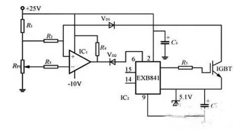
Figure 7 uses IGBT overcurrent Vce to increase the principle of protection
Figure 8 is the use of current sensors for overcurrent detection of IGBT protection circuit, the current sensor (SC) primary (1 turn) in series in the IGBT circuit, the secondary induction of the over-current signal rectified and sent to the comparator IC1 , The IC1 output is fed to the comparator IC2 with positive feedback, and the output is connected to the output control pin 10 of the PWM controller UC3525. The output of the IC1 is fed to the comparator IC2 with positive feedback. However, the current, VA "Vref, VB = 0.2V, VC" Vref, IC2 output low, PWM controller to work properly.

(A) Circuit schematic
(B) Output control waveform of the PWM control circuit
Figure 8 IGBT protection circuit for overcurrent detection using current sensors
When the overcurrent occurs, the rectifier voltage detected by the current sensor rises, VA "Vref, VB is high, C3 is charged to make VC" Vref, IC2 output high (more than 1.4V), turn off the PWM control circuit. Due to no drive signal, IGBT off, and the power to stop working, the current sensor current flow, the VA "Vref, VB = 0.2V, C3 by R1 discharge, when the C3 discharge to the VC" Vref, IC2 and output low If the overcurrent continues, the protection circuit will return to the original current limiting protection working state, repeated cycle to PWM control circuit output drive waveform in the interval output state, as shown in Figure 8 (b) below Waveform. Potentiometer RP1 adjusts the comparator overcurrent action threshold. Capacitor C3 by D5 fast charge, by R1 slow discharge, as long as the reasonable choice of R1, C3 parameters, so that PWM drive signal off time t2 "" t1, to ensure that the power into sleep. Positive feedback resistor R7 to ensure that IC2 only high and low levels of two states, D5, R1, C3 charge and discharge circuit to ensure that IC2 output will not change between high and low, that is, IGBT does not frequently open, turn off and damage The
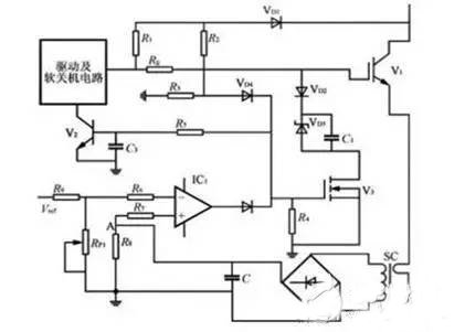
Figure 8 is the use of current sensors for overcurrent detection IGBT protection circuit Figure 9 is the use of IGBT (V1) over-current collector voltage detection and current sensor detection integrated protection circuit, the circuit works is: load short circuit (or IGBT due to other fault overcurrent ), V1 Vce increase, V3 gate drive current by R2, R3 voltage divider to make V3 conduction, IGBT gate voltage by VD3 limit and buck, limit the amplitude of the IGBT peak current, while the R5C3 delay to V2 Turn on, send a soft turn signal. On the other hand, when the short circuit current through the current sensor to detect short-circuit current, the comparator IC1 output high level to V3 conduction down gate voltage, V2 conduction for soft off.

Figure 9 Integrated overcurrent protection circuit
Figure 10 is the application of detection IGBT collector voltage over-current protection principle, the use of soft-gate voltage, soft turn-off and reduce the frequency protection technology of short-circuit protection circuit.

Figure 10
Normal operating state, drive input signal is low, the optocoupler IC4 does not turn on, V1, V3 conduction, the output negative drive voltage. Drive input signal is high, the optocoupler IC4 conduction, V1 cut-off and V2 conduction, the output is driving voltage, power switch V4 work in the normal switch state. When the short circuit fault occurs, IGBT collector voltage increases, due to Vce increase, the comparator IC1 output high, V5 conduction, IGBT to achieve soft drop gate voltage, gate voltage regulator by the regulator VD2 decision, The pressure time is formed by R6C1 for 2μs. (When the voltage on the C2 reaches the breakdown voltage of the regulator VD4, V6 is turned on and formed by R9C3). When the voltage on C2 reaches the breakdown voltage of VD4, V6 is turned on and formed by R9C3. The delay time of the soft turn-off gate voltage, soft drop gate voltage to soft turn-off gate voltage is determined by the time constant R7C2, usually selected at 5 ~ 15μs. V5 conduction, V7 C4R10 circuit through the base current through the conduction of about 20μs, in the gate voltage protection after the input drive signal for a period of time, no longer respond to the input turn-off signal to avoid the formation of the fault state Hard off the overvoltage, so that the drive circuit in the presence of a fault can perform a complete drop gate voltage and soft shutdown protection process.
When V7 is on, the optocoupler IC5 is on, the trigger pin 2 of the time base circuit IC2 gets a negative trigger signal, 555 output pin 3 is output high, V9 is on and IC3 is blocked. The blocking time is determined by the timing element R15C5 1.2s), so that the operating frequency down to 1Hz below the drive output signal will work in the so-called "hiccup" state, to avoid the occurrence of short-circuit fault still work in the original frequency, continuous short-circuit protection lead to heat accumulation caused by IGBT damage. As long as the failure disappears, the circuit can return to normal working condition.
The switching power supply protection function is an additional function required for the electrical performance of the power supply unit. However, it is important to protect the circuit and improve the safety and reliability of the power supply unit in the harsh environment and in the event of an accident. Acceptance of technical indicators, the protection function should be verified.
Switching power supply protection program and circuit structure is diverse, but for specific power supply device, should choose a reasonable protection scheme and circuit structure, so that in the fault conditions to truly effective protection. The protection circuit described in this paper can be used in a flexible combination to simplify the circuit structure and reduce costs.